Documentation

Prepare network data and read Infomap output

Infomap reads plain-text network files and writes the communities it finds in formats suited for downstream analysis, visualization, and reproducible reporting.

Input

6 formats

Start with a link list unless you need node names, bipartite flow, multilayer flow, or state nodes.

Pajek

.net*Vertices + *Edges

Use Pajek when you need a separate node section, node names, or compatibility with existing .net files.

The node section starts with *Vertices N and the link section with *Edges N, *Links N, or *Arcs N, where N is the number of nodes or links.

Text inside quotation marks gives the node name. You can assign node weights by adding a third column with positive numbers. Links are interpreted like the link-list format.

Bipartite

.net*Bipartite

Use bipartite input when links connect two different node types, such as users to items or documents to words.

By default, Infomap adjusts bipartite flow so modules are detected among the primary nodes without first projecting the network. This avoids creating a dense one-mode projection.

The format uses *Bipartite N, where N is the first node id of the feature node type.

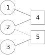
Bipartite network with three round and two square nodes
Bipartite network with three primary nodes and two feature nodes.
# A bipartite network with node names
# Figure 2
*Vertices 5
1 "Node 1"
2 "Node 2"
3 "Node 3"
4 "Feature 1"
5 "Feature 2"
# set bipartite start id to 4
*Bipartite 4
# node_id feature weight
1 4 1
2 4 1
2 5 0.25
3 5 1

Multilayer

.net*Multilayer / *Intra / *Inter
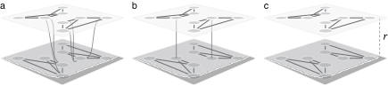
Three multilayer network models
Multilayer network models. (a) Explicit multilayer links between layers. (b) Intra-layer links combined with inter-layer links. (c) Intra-layer links with inter-layer movement set by a relax rate r.

Use multilayer input when the same physical node can appear in multiple layers and movement between layers matters.

Typical use cases include temporal networks where each layer is a time slice, multiplex networks where layers are different interaction types, and coupled networks where the same nodes participate in different systems.

Choose the format based on how much control you need over movement between layers. With *Multilayer, you specify all intra-layer and inter-layer links explicitly.

With *Intra and *Inter, you specify intra-layer links and constrain movement between layers. With only *Intra, inter-layer links are generated automatically from the relax rate.

Full multilayer input with two layers and explicit links between layers.

State network

.net*States
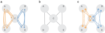
Two-step paths represented as a memory network
Two-step paths represented as a memory network. (a) Two-step paths through the central node C show two distinct flow patterns. (b) A first-order network around C cannot tell them apart. (c) A second-order memory network splits C into state nodes that remember the previous step, separating the flows.
Temporal data, standard network, and memory network
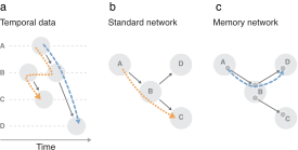
Standard networks destroy temporal information. (a) Interactions along a time axis: the orange walker would have to move backward in time, breaking causality, while the blue walker guided by state nodes obeys it. (b) A first-order network allows the orange step because it ignores time. (c) A memory network constrains flows to follow the temporal ordering.

Use state input for memory networks, multilayer networks, and advanced workflows where internal state nodes should be explicit.

State networks are the most general input format. They subsume multilayer networks and capture higher-order patterns like memory effects in pathway data, sparse multimodal interactions, or any flow that depends on where a walker came from, not just where it is.

The *States section describes internal nodes as state_id physical_id [name]. The state id is then referenced in the *Links section.

The *Vertices section is optional and follows the Pajek format. It is used to name the physical nodes.

Network JSON

.jsonnodes + edges

Use the infomap-network JSON format when you generate networks programmatically or want one structured format that covers standard, bipartite, multilayer, and state networks.

Every file sets format to infomap-network and version to 1.0. The required edges array lists links as source, target, and optional weight. The optional nodes array names physical nodes and can set weights, metadata, or an initial partition path.

The type field selects the network kind: standard (default), bipartite (with bipartiteStartId), multilayer (with multilayer set to full, intra, or intra-inter and per-edge layers), or state (with an explicit states array). Set directed to true for directed links.

A plain network. Only edges are required; the nodes array is optional and used here to name the physical nodes.

Self-links: since v2.0.0 Infomap counts self-links by default. Pass --no-self-links to exclude them. For undirected networks, Infomap follows the convention of counting self-links once.

Output

5 formats

For most workflows use .clu for flat assignments and .tree for hierarchy. Write several outputs with -o tree,ftree,clu.

Cluster file

.clu-o clu

Use .clu when you need a compact node-to-module assignment. This is usually the easiest output for downstream analysis.

By default, .clu outputs the top-level module assignments. To specify another level, use --clu-level <i>.

If the .clu file is used as an input clustering to Infomap, the flow column is ignored and may be omitted.

# module level: 1
# id module flow
1 1 0.214286
2 1 0.142857
3 1 0.142857
4 2 0.214286
5 2 0.142857
6 2 0.142857

Tree

.tree-o tree

Use .tree when you need the full hierarchy. Each row contains the module path, node flow, node name, and node id.

Module assignments are colon-separated from coarse to fine level. Modules within each level are sorted by the total flow of the nodes they contain.

The integer after the last colon is the rank within the finest-level module. The decimal number is the steady-state probability of the random walker in that node.

# path flow name node_id
1:1 0.214286 "1" 1
1:2 0.142857 "2" 2
1:3 0.142857 "3" 3
2:1 0.214286 "4" 4
2:2 0.142857 "5" 5
2:3 0.142857 "6" 6

Flow tree

.ftree-o ftree

Use .ftree when you need the hierarchy plus flow links inside each module.

It extends .tree with *Links sections for child-node flow within modules. The first line states whether the links are undirected or directed.

Links entering or leaving a module are not listed directly, but the corresponding flow is aggregated into enterFlow and exitFlow.

Newick

.nwk-o newick

Use Newick when you want to inspect or process the hierarchy with standard tree tooling.

The format is compact and useful for dendrogram or phylogenetic-style tools that understand parenthesized tree structure.

(((1:0.166667,2:0.166667,3:0.166667):0.5,(4:0.166667,5:0.166667,6:0.166667):0.5):1);

JSON

.json-o json

Use JSON when integrating Infomap output into applications.

JSON preserves structured metadata and avoids parsing text formats. It is the best output when another app or pipeline will consume the result directly.

Output header

Every output file starts with a header that records the run.

# v2.16.0
# ./Infomap network.net . --ftree --clu
# started at 2026-05-05, 07:23:30
# completed in 0.114 s
# partitioned into 2 levels with 2 top modules
# codelength 2.32073 bits
# relative codelength savings 9.22792%

Infomap version

Exact command-line invocation

Run timestamp

Wall time

Hierarchy depth and top-level count

Total description length

Savings versus one-level baseline

Codelength savings

The relative savings measures how much shorter Infomap's modular description is compared to the one-level baseline. Higher means stronger modular structure.

where is the codelength and is the one-level codelength.

Physical and state-level output

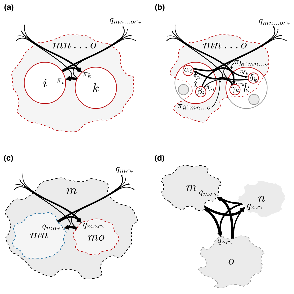
For ordinary networks, output rows refer to physical nodes. For memory, state, or multilayer networks, Infomap can also write state-level outputs. State-level files keep internal state nodes separate; physical outputs merge states that represent the same physical node when possible. Higher-order networks write two files for each of clu, tree, and ftree; the extra file has _states appended before the extension.

Physical and state nodes in output
Network flows at different modular levels. Large circles represent physical nodes, small circles represent state nodes, and dashed areas represent modules.

Read next

How Infomap works
MapEquation

A research framework for understanding flows on networks.

Software

InfomapApps & Notebooks

© 2008–2026 mapequation.org · Terms

martin.rosvall [at] umu.se · Made at Umeå University